Declare the sky before declaring an angle
Choose a propagation direction . The electric field of a transverse wave lies in the plane perpendicular to it. Choose orthonormal axes in that plane. In the Lab’s infrared observation, light travels along , so the sky axes are . The main scene instead shows an side projection; moving the display viewpoint does not redefine the observer.
For many incoherent waves, average the products of their complex electric-field amplitudes. This gives a two-by-two coherency matrix . We normalize its trace to the relevant intensity or ray power. Its diagonal elements describe the two linear modes; its off-diagonal terms retain the information needed when the preferred direction lies between our axes.
Stokes is the total. Positive means more power along the first sky axis; negative means more along the second. distinguishes the two diagonal directions. The present real, absorbing tensor does not generate circular polarization, so we do not infer a missing circular signal from it.
Reading: Hensley & Draine, arXiv:2208.12365v1 (2022) · Dust absorption, heat and polarization: standalone science
Represent the material’s orientation dependence
Let be a unit vector specifying an unoriented alignment axis. The teaching material has scalar opacity multiplied by a positive tensor . The contrast lies between zero and one half. Along the eigenvalue is ; in the two perpendicular directions it is .
Only electric fields transverse to the ray matter, so project into its sky plane. For a uniform column the amplitude propagation matrix is . Then . The half belongs in the amplitude exponent; intensity attenuation already follows after multiplying by its conjugate. Squaring an intensity attenuation again would remove too much power.
The tensor prescribes an absorption difference. It does not calculate how torques align grains, how alignment varies with size, or how a magnetic field evolves. The field-direction handle changes this input axis. Its length is a direction guide, not a measure of magnetic strength.
Reading: Dust absorption, heat and polarization: standalone science · Hensley & Draine, arXiv:2208.12365v1 (2022)
Worked slab: the two modes exchange their advantage
Put along the first sky axis and take . The two mode opacities are and . Illuminate a uniform slab with unpolarized unit intensity, half in each mode. At reference optical depth , the outgoing mode intensities are and .
Their sum is and their fractional difference is . Transmission favors the first direction because that direction loses less light. This is a homogeneous-slab analytic check, not a fit to a particular star.
Now consider optically thin thermal emission from the same material along the same direction. Its mode powers are proportional to their absorptivities, not their surviving transmissions. Thus . The negative sign places the thermal electric-field axis perpendicular to the transmitted one. It is not a negative total intensity.
A whole cloud adds cells with different temperatures and weights. It also sees source rays that need not point toward our observer. The slab explains the local sign and provides an independent limit; it does not permit us to compare angles measured in two different ray planes without projecting them first.
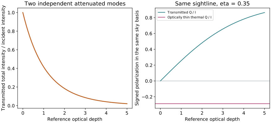
Reading: Dust absorption, heat and polarization: standalone science
A direction has two Stokes angles
The observable linear polarization fraction is . When it is nonzero, the electric-field position angle is . The half-angle reflects a physical symmetry: a line and the same line rotated by describe the same electric-field axis.
As an analytic check, actively rotate an entire physical configuration by around the observer direction while keeping the sky axes fixed. The Stokes vector rotates by . A rotation reverses both and ; the image rotates and is unchanged for this globally rotated source–cloud problem. This is a whole-configuration test in the scientific replay, not a claim that rotating only the field in a fixed illuminated cloud leaves heating unchanged.
Reversing leaves unchanged. Looking along it makes the two transverse tensor eigenvalues equal, so polarization vanishes. At zero polarization the position angle is undefined, so the direction bar disappears.
Reading: Dust absorption, heat and polarization: standalone science
Why an angle is not a three-dimensional field measurement
A small polarization fraction has several possible causes: a direction close to the line of sight, weak alignment, different orientations canceling within a beam, or extra unpolarized emission. The toy cloud uses a single prescribed axis, but real clouds need not. One observed fraction cannot distinguish all these explanations.
The native Astrodust model also has wavelength-dependent material properties, a size distribution and a fitted alignment function. Its signed polarization cross sections can behave differently from the simple positive-contrast tensor. Keep those material-model predictions separate from this derivation.
The Lab lets us isolate projection: choose the line-of-sight preset and then the diagonal-direction preset. The handle sets the input axis; the Stokes output shows its projected radiative effect. In an observation, the inverse problem needs additional geometry and alignment assumptions, with their uncertainties stated.
Reading: Hensley & Draine, arXiv:2208.12365v1 (2022) · Dust absorption, heat and polarization: standalone science